This document describes the software
development methodology followed by Inooga Solutions.
If any of the project development needs a deviation because of any specific
nature of the project / product deviates from any of the aspects of the
methodology defined here, the same is justified and approved by the business /
department - head.
The document provides the software
development life cycle models adopted by Inooga
Solutions for software development of the following:-
Ø
Execution
models for software development projects along with design methodologies.
Ø Execution model for software maintenance projects.
Intended users of this document
include: -
Ø All the project personnel.
Ø Quality department personnel.
Ø
Internal auditors.
Ø Review committee.
1.3 Terms
and definitions
|
Abbreviations/Terms |
Description |
|
QMS |
Quality
Management System |
|
ISPL |
Inooga
Solutions Pvt.Ltd. |
|
PM |
Project
Manager |
|
PL |
Project
Leader |
|
TM |
Team
Member |
|
ML |
Module
Leader |
|
WBS |
Work
Break Down Structure |
|
SDLC |
Software
Development Life Cycle |
|
CASE |
Computer
Aided Systems Engineering |
2
Software development
methodology
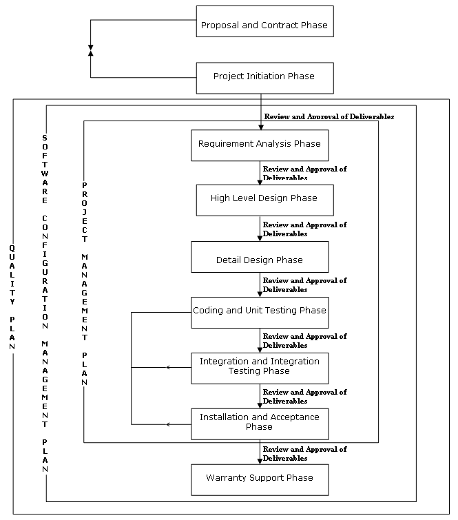
Software development methodology
adopted by Inooga Solutions has the following phases:
Ø
Requirements analysis phase.
(Requirements definition, proposal & contract, project
initiation).
Ø
High level design phase.
Ø
Detail design phase.
Ø
Coding & unit testing phase.
Ø
Integration & integration
testing phase.
Ø
Installation & acceptance phase.
Ø
Warranty
1 3 SDM diagram
The various life cycle models
followed in Inooga Solutions for executing software
development projects/products are
Ø Waterfall model.
Ø Incremental model.
Ø Prototype model.
Ø Spiral model.
Some of the projects scope may
require that only some of the phases are applicable in which case the entire
life cycle activities may not be applicable. The project manager identifies the
appropriate life cycle model along with the applicable life cycle activities
and documents the same in project management plan of the respective project.
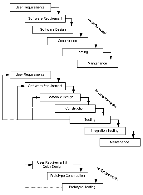
Figure illustrated below is the
“waterfall model”. This life-cycle model demands a systematic, sequential
approach to software development that begins at the customer’s software requirements
and progresses through analysis, design, coding, testing and post development
warranty.
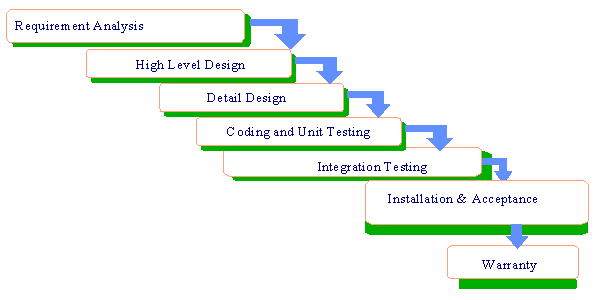
Suitable for projects where:
Ø
Requirements
are clearly defined.
Ø
They are of any size and any sort of
duration.
Ø Stable technology.
Ø Familiarity with the domain and development
environments.
The phases of waterfall model are as under -
Ø
Requirements Analysis.
Ø
Design.
Ø
Construction & unit testing.
Ø
Integration/system testing.
Ø
Acceptance testing.
Ø
Delivery.
Ø
Maintenance.
The project takes a "Straight
line" path. The different phases are explicitly recognized and the
subsequent phase starts only after completion of the previous phase.
In this model, since the subsequent
phase is dependent on the previous one, the scope for revisiting a requirement
at a later stage is not there. Customer sign off for user requirements and
subsequent documents up to the design stage (where feasible) should be taken to
ensure clarity in requirements and reduce subsequent changes and rework.
Alternatively, customer feedback may be taken from time to time.
Usage - Waterfall model is suitable for small projects and
projects where the user needs are clearly specified.
Advantages:
Ø
Projects
under control.
Ø Pre-defined outputs at every phase.
Ø
Tracking changes is easy.
Ø
Early identification of slippages, if
any.
Disadvantages:
Ø
In real life, customer requirements
do change.
Ø Customer appraisal of completed work - not feasible
always.
Ø
Phases
cannot run concurrently.
The interconnection among the SDLC phases in the waterfall model is as follows:
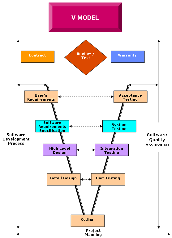
Waterfall
model is also known as ‘classic life cycle model’, ‘linear sequential model’.
This model suggests a systematic and sequential approach to software development
that begins at requirements analysis and progresses through all life cycle
phases sequentially:
Ø
Development
associated tasks carried out sequentially.
Ø
Review and
approval of each phase outputs.
Ø
Model does
not permit going back and forth.
Ø
If any defect found, go back to the
originating phase and start traversing sequentially all over again.
Incremental model is like an iterative
waterfall model, with new iteration taking up new functionality. Typically in
this model, the core of the application is built initially and components are
added to it periodically. This permits gradual implementation of the system in
small installments and reduces implementation risk.
The obvious advantages are savings
on implementation resources, early operation of the system and reduction in the
impact of project failure.
All phases will be similar to
waterfall model, but restricted to a particular module. Based on the logical
ERD, a base physical data model is created and construction phase starts after
that. Completion of design for each module may result in change in database and
may also impact some already completed modules. For such impacted modules
design will be updated and again build and corresponding phases will start.
On completion of all the modules,
integration testing is done. It is possible to have iteration of integration
testing also. This can happen if a project is broken up in delivery phases with
critical and dependent modules being taken up in earlier phases.
Usage - This model can be used for a project of any size where
the application can be developed in a modular fashion with minimum
interdependency.
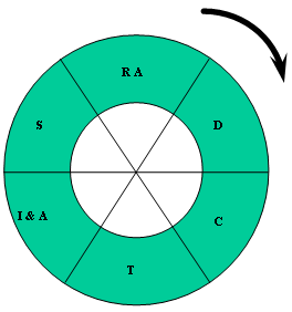
In this model, software is developed
in a series of ‘incremental’ releases. The spiral model is divided into a
number of framework associated tasks or task regions:
Ø Suitable for large projects with multi-location
implementation.
Ø
Each spiral consists of a deliverable
product.
Ø
Feedback
of each spiral is incorporated in the next spiral.
Ø
Customer
can start using the system after every spiral.
Ø
Each spiral consists of a waterfall
model.
Ø Risk evaluation at any point of a spiral and
formation of a new spiral as a result of this.
Advantages:
Ø Useful for large projects.
Ø
Customer
requirements evolve over a period.
Ø
Early availability of usable system.
Disadvantages:
Ø
Total blue
print should be available in the beginning.
Ø
Basic
concepts in the underlying layer cannot be changed.
The prototyping strategy is
increasingly being used. It gives a feel of the product in the early stages and
how it will work in the future. It is also a useful model when -
Ø
There is a requirement to demonstrate
feasibility of a core concept / design attribute.
Ø
There is a requirement to demonstrate
the user interface or a subset of the total requirements.
Ø
There is a need to elicit a market
response.
Ø
Requirements
are not clear and they have to be elicited interactively for freezing the user
requirements.
End users who make recommendations
about requirements review the prototype system. The prototype is then enhanced
or refined to reflect end users requirements. Prototyping makes such revisions
possible.
Prototyping can be of 3 types -
Ø Rapid application development (RAD) model.
Ø Evolutionary.
Ø Throw Away.
Advantages:
Ø
Can be used when customer is not sure
about a faster way of finalizing the requirements.
Ø Useful for new technologies and domains.
Disadvantages:
Ø A prototype if used in a
production environment may lack quality or maintainability.
4.4.1
Rapid application development (RAD) model
The project begins with requirements
gathering concentration on the purpose and scope of the application. A quick design
focusing on representation of the core aspects of the system is prepared and
documented. The prototyping tool is used to create screens or reports using
case tools along with navigation headings, comments, help messages and error
messages. Once this is completed, the screens are demonstrated to end users and
normal operation is simulated. The end users provide feedback about what needs
to be added, deleted or changed. This may go through a few iterations before
the design is finalized. Once the design is approved, the code is generated in
the suitable technical environment.
Usage - When CASE tools or front-end tools like Visual Basic, Power
Builder or Developer 2000 are being used and the user knows the requirements,
this type of prototyping is used.
4.4.2
Evolutionary model
This model goes through a
cycle–(Requirements->Quick Design->Construct->Test->Evaluate) - a
number of iterations until the product is acceptable
to the customer in terms of meeting the objectives and the functional
requirements. The project begins with requirements gathering concentration on
the purpose and scope of the prototype. A quick design focusing on
representation of the core aspects of the system is prepared and documented.
The criteria for start / end of iteration and the final cut are also
documented. Major functions are developed early in the project schedule. Since
continuous feedback is taken from the customer, additional functionality may be
added from time to time, as the product takes shape. Once the product is
accepted, the other activities of documenting the system and implementation are
performed.
Usage - This model is used when the user is not clear about his
requirements. The prototype helps the user get a feel of the system. With
continuous feedback from the customer and subsequent refinement of the
prototype, the final application meeting customer requirements is developed.
4.4.3
Throw away model
Development
model, where work initiates after understanding the requirements and arriving
at the right solution. This
development is done in a quick manner implementing the applicable standards.
The requirements and solutions are finalized and a fresh development is started
using any of the life cycle models applicable at Inooga
Solutions. The tools/software used for development of this prototype may not be
the one, which is to be used for the final development. This can also be a
paper prototype.
Usage - Sometimes the user knows about his requirements (not
completely) but is hesitant about the type of solution and system provided. In
such a case, a throw away prototype is developed, and if the user is satisfied
with the solution proposed, the final system can be developed accordingly.
5
Execution models for
software development projects
5.1
Design
methodologies
The
major goal of the design methodologies is to provide methods and techniques
based on engineering and software science, to clearly and unambiguously specify
the solution with as much clarity as in the mode of documenting the
specification(s).
In this
document, we consider the following three methodologies:
Ø Structured system analysis and design (SSAD).
Ø Information
modeling.
Ø Object
oriented analysis and design (OOAD).
A brief
phase overview of these models is presented here.
5.1.1
Structured system analysis
and design (SSAD)
SSAD is one of the oldest design
methodologies. This is a predominantly process oriented methodology. Since its inception,
it has evolved to a mature model and has spawned many variants, each of them
being quite stable. This document will not provide the details of the
methodology, but will explain the philosophy of analysis and design based on
this method.
SSAD methodology is a process
centric view of the software product. These processes are connected by data
flows, which provide the necessary data (information), needed to proceed with
the computations. This methodology proposes
Ø A static model, which provides the processes and the data flows.
Ø A
dynamic model which describes how each of the processes behave given the set of
inputs (flows)
The methodology has a set of rules
by which the documentation of the system using the notations can be validated
for syntactic consistency. Tools also exist which automatically validate the
model similar to the rules of SSAD notational rules.
The static model consists of a level
zero diagrams, which relates the external environment and the computational
model of the solution. Subsequent levels of details are evolved as the analysis
and design progresses. The data flows are logical and are treated as stores
(secondary media). The modeling of the stores is based on the E-R modeling
technique. These stores traditionally end up as databases and file systems.
In the dynamic model, state
transition diagrams are used to express the time dependent behavior of the
processes. These state transition diagrams trace the application flow based on the
events that occur either in the external world or as a result of internal
processing. The extensions of these transition graphs are the timed transition
graphs, which are used widely for developing real-time systems.
A data dictionary is constructed to
record the characteristics of all the identified entities (data flows,
processes). This repository of the various names and their attributes provides
a consistent (uniform) framework for assisting the analysts/designers in
stating, analyzing d visualizing the solution.
The best advantage of this
methodology is that it expresses parallelism at the design level. The
dependency of the processes is with respect to the data and not control flow.
The processes can be initiated whenever the necessary data (flow) is available.
This simplifies the partitioning of the coding associated tasks.
5.1.2
Information modeling
This
methodology is data-centric and the analysis and design is strongly based on
the Entity-Relationship (E-R) model. The methodology specifies that all the
computations and data transformations be relative to this model. Each
computation and the transformation of the data are derived from the information
the user is interested in. This model provides the end-user view of the system
and describes the information flow between the entities. Processes are viewed
as data transformers and are linked to the E-R model entities. The essential
difference between the SSAD and the information modeling technique is the
manner in which the solution is derived. The end result in both cases is the
same. In case of this methodology, the
process starts with the E-R model and the data transformers (processes) are
bound closely to the entities. The design of the processes is similar to the
SSAD technique. Apart from the philosophy of the “VIEW” - the data being
prominent and the unifying factor of all the processes that exist in the
problem domain in this method, the rest of the solution derivation process is
similar to SSAD method.
The major advantage is that the methodology
provides excellent
5.1.3
Object oriented analysis and
design (OOAD)
Object oriented methodologies
closely represent the problem domain, which makes it produce and understand
design. As requirements change, the objects in a system are less immune to
these changes thereby permitting changes more easily. Due to inheritance and
close association of objects in design to problem domain entities, Object
oriented designs encourage more re-use. Object oriented design is more natural
which provides nice structures for thinking and abstracting that leads to
modular designs.
Steps in OOAD are:
Ø Object modeling.
Ø Dynamic modeling.
Ø Functional modeling.
Ø
Internal classes and operations.
Ø Optimization and package.
5.1.3.1 Object modeling
The system is viewed as consisting
of objects. The objects interact with each other through the services they provide.
Some objects also interact with the users to provide the desired services to
the users. The goal of object modeling is to define the objects that exist in
the problem domain, specify the information they encapsulate, identify their
relationship and define the services provided by them.
5.1.3.2 Dynamic modeling
Dynamic model specifies how the
state of various objects changes when events occur. For an object, an event is a request for an
operation. Event has an initiator and responder. Events can be internal or
external to the system. Events of the same type are grouped together as event
classes. A scenario is a
sequence of events that occur in a particular execution of the system. Different scenarios together characterize the
behaviors of the system.
Major steps in dynamic modeling are:
Ø Prepare scenarios of typical interaction sequences.
Ø
For each scenario identify the events
between objects and prepare event traces.
Ø
Build
state diagrams.
Ø Match events between objects to verify consistency.
5.1.3.3 Functional modeling
Functional model describes the
computations that take place within the system. It is the third dimension in
the modeling. Object model looks at the static nature of the system and the
dynamic model looks at the events in the system and the functional model looks
at the functionality of the system.
A functional model specifies how the
output values are computed in the system from the input values without considering
the control aspects of computation. Functional model can be represented by data
flow diagrams.
In other words, functional model
specifies what happens in the system, dynamic model specifies when it happens
and object model specifies what happens.
5.1.3.4 Inter classes and
operations
At this stage, each object is
critically evaluated to see if it is needed in its present form in the final
implementation. Some objects may be discarded. Rough algorithms are created.
Implementation of each class and each operation on the class is considered.
5.1.3.5 Optimization and
package
At this stage using some of the
techniques given below optimizes design:
Ø Adding redundant associations.
Ø Saving derived attributes.
Ø Use of
generic types.
Ø Adjustment
of inheritance.
6 Execution model for
software maintenance projects
This model is applicable for
maintaining existing customers system or for providing post delivery
warranty/maintenance
Ø
System study and knowledge
acquisition.
Ø
Inventory and baseline.
Ø
Preparation of maintenance
guidelines.
Ø
Execution of maintenance requests.
6.1 System
study and knowledge acquisition
The existing system is studied to
understand the application, application environment (i.e., hardware/software
platform and tools used) and scope of the maintenance
Ø Sending members of the maintenance team to the customer's
site to interact with
the users or existing maintenance team and understand the
application/environment.
Ø Providing training by Customer's representative/ existing Maintenance
Team on
the application and environment.
The maintenance team assigned by Inooga Solutions obtains all necessary documents like
user/system/technical manuals, any training material available on the
application / tools / environment and any other documentation customer can
provide for better understanding of the application. The application knowledge
thus gained is transferred to other maintenance team members through formal
training and on the job guidance.
A pilot is recommended in case the
software/environment used is new to the organization, scope and service levels
are not clear or the project is large. The results of the study/pilot are used
for -
Ø
Effort estimation.
Ø
Resource planning.
Ø
Fixing scope of the maintenance
project.
Ø Essential application documentation (This may not be
required in case
adequate application documentation is provided by the customer or is
available).
Ø
Preparation of maintenance
guidelines.
Ø
Identification / preparation of
coding standards.
Ø
Verification & validation
strategy.
Acceptance criteria and procedure
for acceptance are also agreed upon by Inooga
Solutions and customer during this phase.
6.2 Inventory
and baseline
In this phase, the maintenance
environment is setup, inventory of the application to be maintained is
catalogued and a baseline of the application is done. The maintenance
environment is typically setup in two ways -
Ø
The application resides on the customer's systems with access
provided to the Inooga Solutions maintenance team. In
this mode, Inooga Solutions maintenance team logs
into the customer's system and the configuration management and system
administration is the responsibility of the customer unless otherwise specified
contractually.
Ø
The customer provides a copy of the application or provides
access to download the same from the customer's system to Inooga
Solutions system. The configuration management and system administration
responsibilities lie with Inooga Solutions in this
case. However, configuration management at the customer's end still remains the
responsibility of the customer unless specified contractually.
All the programs, screens, reports,
and databases and any other related components constituting the application are
identified and catalogued to find the number of items that are to be
maintained. Alternatively, this information may be provided by the customer or
available as part of the documentation. Any changes to the inventory are
managed using the configuration management procedure. Impact due to change in
inventory on effort/schedules are analyzed and work order/contract amendments
are obtained where required.
6.3 Preparation
of maintenance guidelines
The applicable coding standards,
maintenance guidelines (e.g., norms for check-In / check-out and acceptance
etc.) are identified and documented in this phase. The maintenance guidelines at
a minimum should address the following -
Ø
Applicable coding standards.
Ø Service levels for various maintenance requests.
Ø
Escalation procedure.
Ø Any norms to be followed while accessing the customer's system.
Ø Tools/techniques used specifically for maintaining this
system.
Alternatively, if the customer sends
the guidelines and coding standards, the offshore team reviews the same for any
concerns in understanding and gets the same incorporated in the documents provided
by the customer, before maintenance is started.
6.4 Execution
of maintenance requests
The maintenance requests are
classified broadly as follows -
Ø
Production
Ø Bug fixing/ program change request.
Ø
Enhancement request.
Ø
Customization request.
The maintenance projects undertaken
by Inooga Solutions may have one or more of the
above-specified activities based on the scope of the maintenance contract. The
broad criteria for classification of activities in maintenance projects are
given below -
|
Sl.No |
Classification |
Work description |
Size/ estimation |
Applicable Procedure |
|
1. |
Production
Support |
Problems
encountered during production runs. Task
not preplanned by the customer. Response
times are pre-fixed based on set levels of priority with the customer at the
start of the project itself in most cases and are applied to the tasks
accordingly. Mode
of communication is by e-mail or phone or by logging into a tool etc., as
agreed with the customer to minimize elapsed time. |
Turnaround
time is a few hours to a few days. If a production |
Production
(See
6.4.2 section. below) |
|
2. |
Bug
Fixing/ Program Change |
Small
problem logs for resolution. Typically involves fixing the analyzed bug by
making minor modifications to one or more source components. Planned
activity. |
A
few hours to a few days. The estimation is done for each task and agreed with
the customer. |
Bug
fixing/ program change procedure (See
6.4.2 section below.) |
|
6. |
Enhancements |
Requests
for enhancing the functionality or performance of the existing application.
Typically involves functional changes affecting large number of programs or
involving new program development. |
Each
enhancement ranging from a few weeks to a few months. Estimation based on
formal estimation techniques specified in estimation procedures. |
Enhancement
& customization procedure (See
6.4.2 section below.) |
|
7. |
Customization |
Customer
requires adaptation of an existing application to a changed requirement. This
is typically done when an application is to be used at multiple locations
with some modifications. The baseline version and the versions of the
customized application are in use simultaneously. |
Each
customization request ranges from a few weeks to a few months. Estimation
based on formal estimation techniques specified in estimation procedures. |
Enhancement
& customization procedure (See
6.4.3 section below.) |
Note: The nomenclature mentioned
above is only indicative and different nomenclature may be used for different
customers. The PMP records the specifics chosen for the project.
6.4.1
Bug fixing / Program change request
1. A request explaining the problem and the changes/fix
expected is received from the client. This may be received through a client's
problem tracking system, an email or a fax or orally over telephone/voice link.
2.
The request is logged using the
maintenance request form (QMS-ISPL-F-MRF) and tracked using a status tracker.
The status tracker can be a tool (e.g., DCS, iPlan,
MS-Project) or a register maintained on a spreadsheet application (e.g. Excel).
3.
The TM estimates the effort required
and obtains approval from the client about the effort required and the delivery
date. In case predefined service levels exist, the same becomes the basis for
determining the delivery date. In case the service levels or a customer
specified delivery date cannot be met, the reasons and the possible delivery
date are escalated to client.
4.
The problem/change is analyzed and
the specifications are documented in the maintenance request form where no
previous design documentation exists. In cases where the design documents are
available the same are revised.
5.
If contractually required, the
specifications are forwarded to the client for review and signoff.
6.
The TM prepares the
unit/integration/regression test plans applicable for the program, changes and
makes the necessary program changes based on specifications. The TM tests the
modified programs as per the test plan and rectifies any defects found.
7. A reviewer designated by the PL/ML reviews the modified
programs and the test results as per the Review procedure. Any defects identified
are tracked to closure before delivering the program changes.
8. The program changes along with any associated documentation
e.g., test plans, if required by client, are delivered as per the delivery
procedure.
9. On-site coordinator/client reviews/tests the deliverables
and accepts the same. The request is closed on receipt of acceptance.
10. The knowledge base of the project is
updated if the request serviced is of a new type or any additional knowledge
was gained when resolving the request.
11. The status tracker is updated for
the closure date and time.
6.4.2
Production
1. A request mentioning the problem and seeking
2. The request is logged in a status tracker. The status
tracker can be a tool (for example, DCS, iPlan) or a
register maintained on a spreadsheet application (for example, Excel).
3. If the TM cannot resolve the problem within the service
levels or due to inadequate application knowledge, the same is escalated to
client representative as per the escalation procedure documented in PMP.
4. The TM refers the knowledge base of the project to see if a
similar problem has been resolved earlier. If the knowledge base contains
relevant information, the same is used to service the request. If no relevant
information for the request exists in the knowledge base, the problem is
analyzed and serviced by the TM. If any changes are required in the code /data
files, the changes are made as per the maintenance guidelines and coding
standards applicable for the project and tested.
5. If the analysis indicates that more time is required to
service the request than the agreed service levels permit, the same is
escalated to client representative as per the escalation procedure documented
in PMP. A temporary fix may be provided and the request is logged as a Bug
fix/program change request (or any other type of request based on analysis).
The request is then serviced as per the methodology indicated for the given
type of service request.
6. Once the problem is resolved, the same is communicated to
the client and the call is closed after the acceptance / approval of the same.
7. The knowledge base of the project is updated if the request
serviced is of a new type or any additional knowledge is gained when resolving
the problem.
8. The status tracker is updated for the closure date and time.
6.4.3
Enhancement/customization
1. A request explaining the scope of the
enhancement/customization is received from the client. This may be received
through a client's problem tracking system, an email or a fax or orally over
telephone/voice link.
2. The request is logged in a status tracker. The status
tracker can be the client's problem tracking system or tool (for example, DCS, iPlan) or a register maintained on a spreadsheet
application (for example, Excel).
3. The TM/team estimates effort required and informs the
on-site coordinator/client about the effort required and the delivery date. In
case predefined service levels exist, the same becomes the basis for
determining the delivery date. In case the service levels or a customer
specified delivery date cannot be met, the reasons and the possible delivery
date are escalated to client with intimation to PM.
4. WBS for the enhancement/customization is prepared detailing
all the activities that are required for the enhancement/customization.
5. If the client does not provide the specifications for the
enhancement / customization, the requirement is analyzed and the specifications
are documented using the DFIN template. The TM assigned obtains
information/clarifications from client during analysis.
6. If contractually required, the specifications are forwarded
to the client for review & signoff.
7. The TM/Team prepares the unit/integration/regression test
plans applicable for the program changes before the testing activity begins.
8. A reviewer assigned by the PM reviews the test plans as per
the review procedure. Any defects found are tracked to closure before using the
test plans for testing.
9. The TM/Team codes the source components based on the
specifications as per the construction procedure. The TM/team tests the
modified programs as per the test plan and rectifies any defects found.
10. A reviewer assigned by the PM
reviews the modified programs and the test results as per the review procedure.
Any defects found are tracked to closure before delivering the program changes.
11. The PL/ML nominates one or more
persons for conducting the integration/system testing as per the respective
test plans and the testing procedure. All defects that are identified are
tracked to closure before delivering the application/module to the client.
12. All deliveries affected as part of
executing the enhancement/customization are delivered as per the delivery procedure.
13. The application/module along with
any associated documentation (for example, test plans,) if required by client,
is delivered to the on-site coordinator/client.
14. On-site coordinator/client reviews/tests
the deliverables and accepts the same. The request is closed on receipt of
acceptance.
15. The knowledge base of the project is
updated if the request serviced is of a new type or any additional knowledge is
gained when resolving the request.
16. The status tracker is updated for
the closure date and time.